
3D-Radar Principle of Operation
THE FASTEST STEP-FREQUENCY SYSTEM AVAILABLE
The GeoScope™ GPR is the fastest step-frequency radar on the market. By using a digital frequency source instead of traditional phase-locked loop technology, the GeoScope™ can generate waveforms from 100 MHz up to 3 GHz with as much as 1500 frequencies with waveform lengths of 0.5-10 milliseconds. The step-frequency radar has a coherent receiver which means that the whole waveform length (typically a few milliseconds) is used as 100% efficient integration time. By comparison impulse GPRs use stroboscopic sampling with significant loss of energy.
WHAT IS STEP-FREQUENCY RADAR?
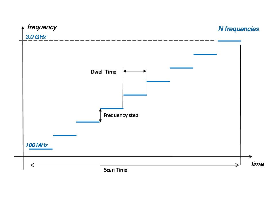
Step-frequency is a radar waveform consisting of a series of sine waves with linearly increasing frequency. The radar measures the phase and amplitude on each frequency and used an inverse Fourier transform of these data to build a time domain profile (A-scan). Thus, the step-frequency radar collects data in the frequency domain and converts the data to time-domain data through computer processing.
The step-frequency waveform gives optimum source signature with a uniform frequency spectrum. The computer control allows the user to set the dwell time on each frequency as well as the start and stop frequencies as shown in Figure 1.
HOW DOES STEP-FREQUENCY DATA DIFFER FROM DATA FROM IMPULSE RADARS?
Impulse radars transmit very short pulses (impulses) with a fixed pulse repetition rate (PRF) and uses stroboscopic sampling to build the time domain trace from several subsequent pulses. Hence, the impulse radar data is the direct reading of the time-domain reflection from the underground. The step-frequency radar data can either be stored as frequency domain data or as time domain data after inverse Fourier transform. The time-domain data from a step-frequency radar are equivalent to time-domain data from an impulse radar. However, the frequency data allows a much wider range of frequency domain processing possibilities.
WHAT ARE THE BENEFITS OF USING STEP-FREQUENCY?
- 100% efficient integration time.
- Fully programmable frequency source signature with full spectrum control.
- The frequency range can be programmed and optimized to each measurement problem. There is no need to waste energy at high frequencies if the soil attenuation is high and medium to low resolution is sufficient for the job.
- The raw measurement data can be stored as frequency domain data. This allows the user to reprocess data with different frequency weighting to enhance the features of interest. It is also possible to perform frequency domain absorption analysis to study phenomena related to concrete delamination.
- The frequency domain data is perfectly suited for fast FK-migration for image focusing.
- The step-frequency signal is a low peak-power signal with low probability of interference with other radio systems. The 3d-Radar step-frequency system only transmits a burst of energy only when it is performing a scan.
- Due to the self-calibration of the system, there is no time-drift in the system eliminating the warm-up time.
The radar system performs real-time time domain conversion through Fast Fourier Transform allowing the user to view B-scans from one antenna at a time. Raw data can be stored on 3DR data format either in time-domain or frequency-domain for post-processing. These data can be imported into either ReflexW from Sandmeier or RoadDoctor™ from Roadscanners OY.
The radar is controlled from a laptop computer through an ethernet cable. The system can also be configured with GPS interface (RS232C) to allow recording of NMEA-0183 position data.
Collect up to 41 survey lines simultaneously
The GeoScope™ GPR is designed to operate with electronically scanned antenna arrays. DX antenna arrays (air-coupled) can be operated at elevations up to 50 cm off the ground allowing high-speed surveys. DXG antenna arrays (ground-coupled) are designed to maximize the energy transfer into the subsoil, providing deeper penetration.
Wideband frequency coverage of the antenna array compared with traditional GPR antennas.
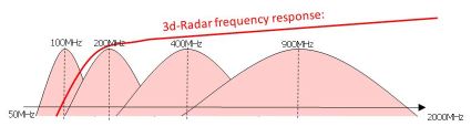
In opposition to traditional octave-band GPR antennas the ultra-wideband bow-tie monopoles have continuous frequency coverage from the 100 MHz range up to 3 GHz as illustrated. In practice this allows the user to collect data from 100 MHz to 3 GHz without changing antennas. By comparison, a similar survey using impulse GPR would require use of 200 MHz, 400 MHz, 800 MHz and 1600 MHz antennas.
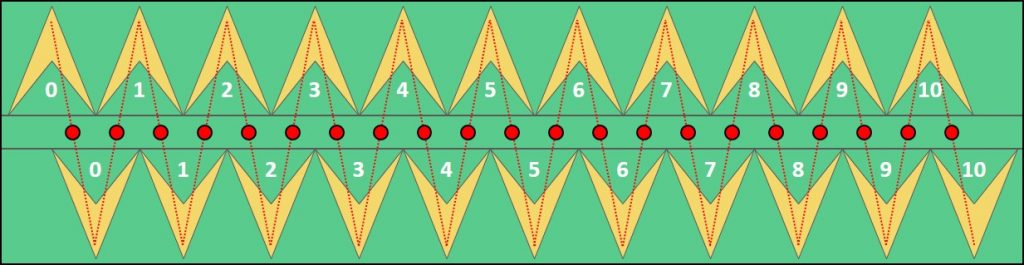
The antenna elements are arranged in a linear array where the transmitting and receiving antennas are displaced to each other. During the survey, the radar combines the transmit/receive antennas sequentially to obtain a number of profiles (or channels).
Placement of the antenna elements in a DX1821 array
Multi-offset recording capability
The Multi-offset recording allows the user to set up antenna scanning sequences with independent transmitter and receiver antenna locations.
With the Multi-offset feature, the system offers a higher degree of freedom to build more advanced scan patterns. It is for example possible to transmit at Antenna #1 and receive at Antenna # 8, (i.e. with an offset distance along the cross-line direction).
User friendly data acquisition and control
The GeoScopeTM is controlled by a laptop PC with any industry standard web browser, using standard 1Gbit/s Ethernet connection. The user software allows you to configure the frequency range, integration time, number of active antennas, and sampling interval for each survey. During data acquisition, the users can view data from one channel at the time and define their own range of markers to be introduced into the data. DMI (Distance Measurement Instrument) calibration is also easy conducted using the step-by-step guidance.
Figure 8 : User Friendly Interface and Real-time 3D display.
Real-Time 3D View
The Real-Time 3D (RT3D) feature of the GeoScopeTM GPR gives the user an instant view of data from every channel from a 3d-Radar antenna array while collecting data in the field.
By displaying simultaneous views of in-line profile (radargram), cross-line profile and a horizontal time slice at a selected depth, RT3D makes field work much easier and enables the user to view and recognize targets while surveying as the objects are showed in Real-Time. This unique feature allows the user to track an object like a pipe while surveying. When coupling the RT3D equipped GeoScope with a GPS, operators can mark directly over the object’s location and have an exact position of the object.
Real-Time performance is achieved by using the built in capabilities of the Field Programmable Gate Array inside the GeoScope. This FPGA converts frequency domain data into time domain data by performing inverse fast Fourier transforms, or iFFTs. The resultant data, when converted into the time domain, truly exploits the multi-channel, step-frequency capabilities of the antenna and GeoScope.
The RT3D view opens many new applications such as real-time landmine, UXO and IED detection, fast and efficient utility mapping and real-time road and bridge inspection. It is even possible to use the RT3D GPR for tracking and guidance when mapping large structures like pipelines and cables.
Why settle for 2 dimensions? - Kontur